WHAT IS FM-200™?

FM-200™ (HFC-227ea) is formed from the elements carbon, fluorine and hydrogen (CF3CHFCF3-heptafluoropropane). The primary extinguishing mechanism of FM-200™ is heat absorption, with a secondary chemical contribution from the thermal decomposition of FM-200™ in the flame.

FM-200™ fire suppressant (HFC-227ea) can be safely used where people are present.

When used at standard design concentrations, it is safe for occupied spaces. FM-200™ leaves no residue. Most common metals, such as aluminum, brass, steel, cast iron, lead, stainless steel, and copper, as well as rubber, plastic, and electronic components, are unaffected when exposed to FM-200™ (HFC-227ea).

FM-200 Suppression Systems

  • Safe for human occupancy.
  • Zero Ozone Depletion Potential (ODP)
  • Discharges in 10 seconds or less to extinguish fires rapidly, minimizing damage to high value assets.
  • Appears on US Environmental Protection Agency (EPA) Significant New Alternatives Policy (SNAP) list
  • Designed in accordance with NFPA 2001.
  • UL listed and FM approved.
  • Marine system with USCG and ABS approvals also available.

FM-200® is a clean, colorless, and environmentally friendly fire suppression agent that is electrically non-conductive and safe for humans. It extinguishes flames primarily through heat absorption, leaving no residue, thus minimizing downtime after a fire and making FM-200 suppression systems accepted and respected worldwide with over one hundred thousand installations in more than seventy countries.

Typical Clean Agent System Layout

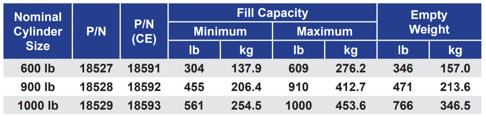
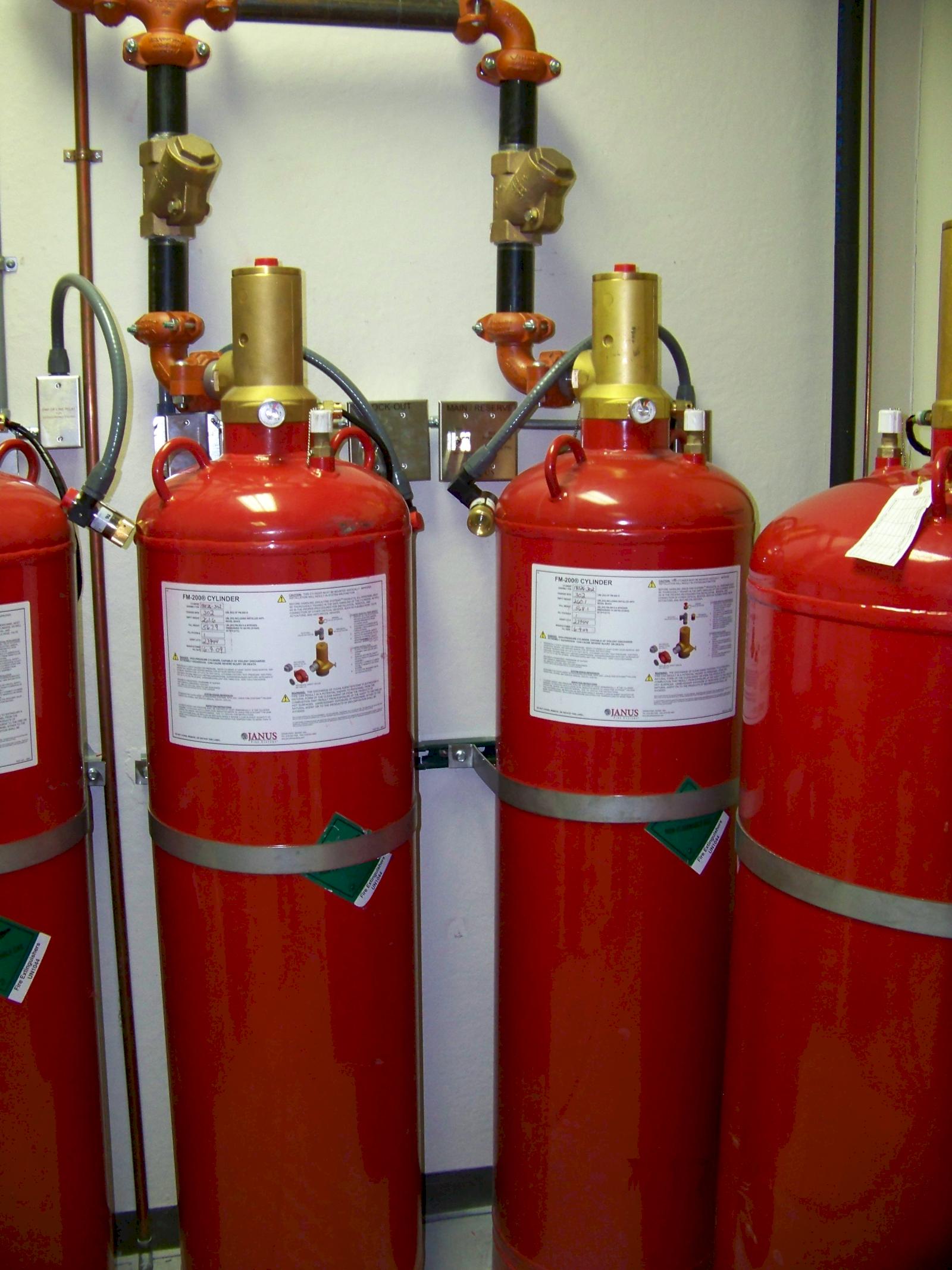
1. FM-200® Storage Components

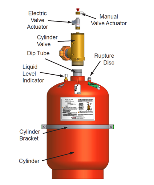
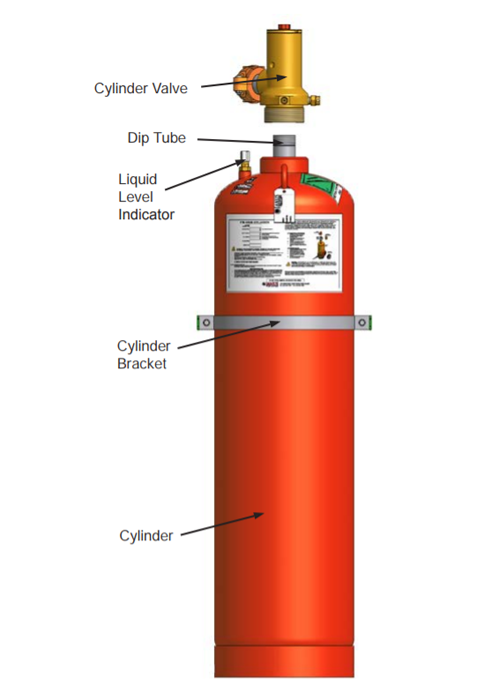
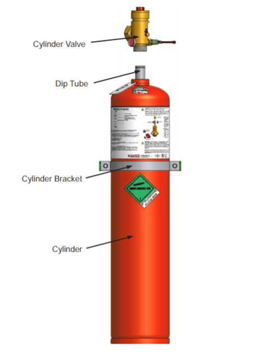
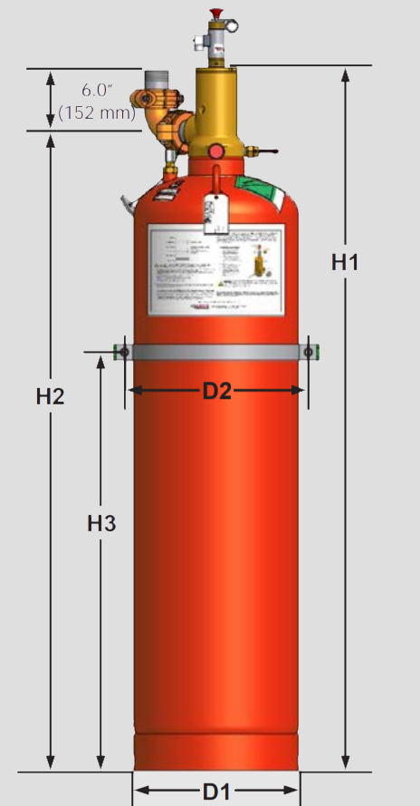
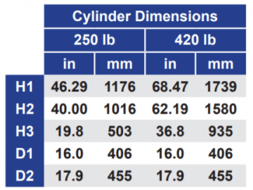
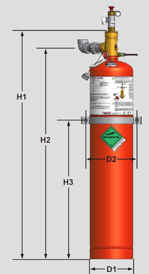
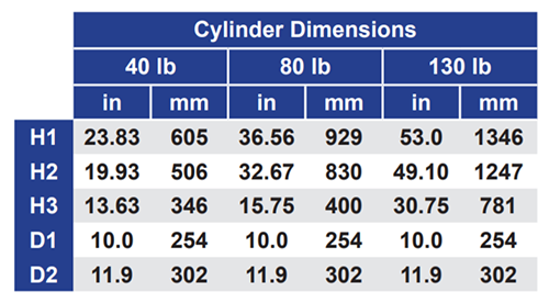
Storage components consist of the cylinder assembly(s), which contains the FM-200® chemical agent, and the cylinder bracket(s), which holds the cylinder assembly securely in place.

2. FM-200® Distribution Components

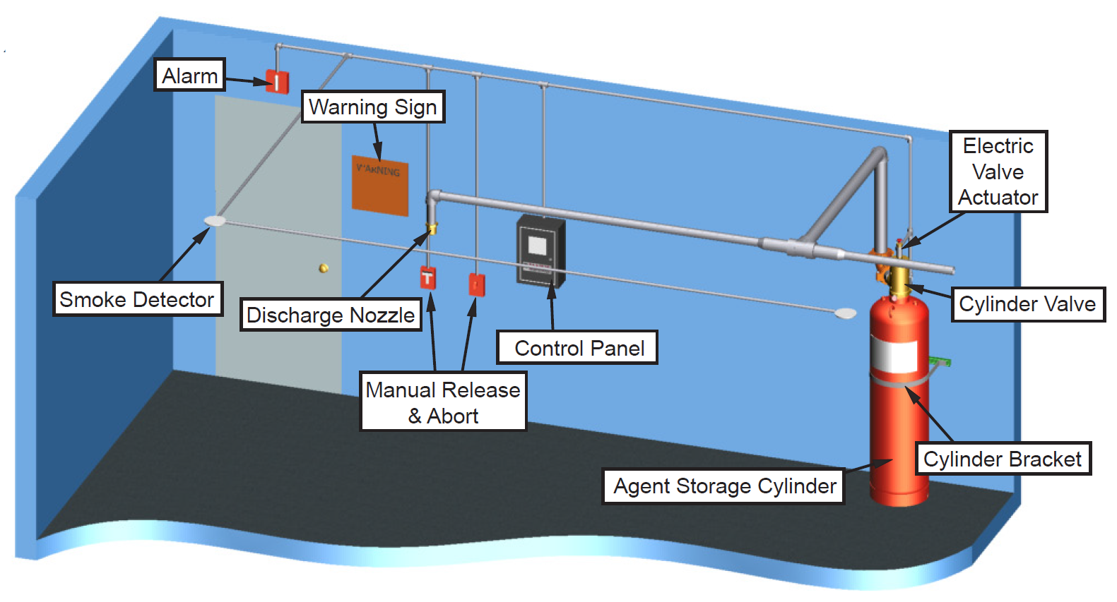
Distribution components consist of the discharge nozzles used to introduce the FM-200® agent into a protected hazard along with the associated piping system used to connect the nozzles to the cylinder assembly.
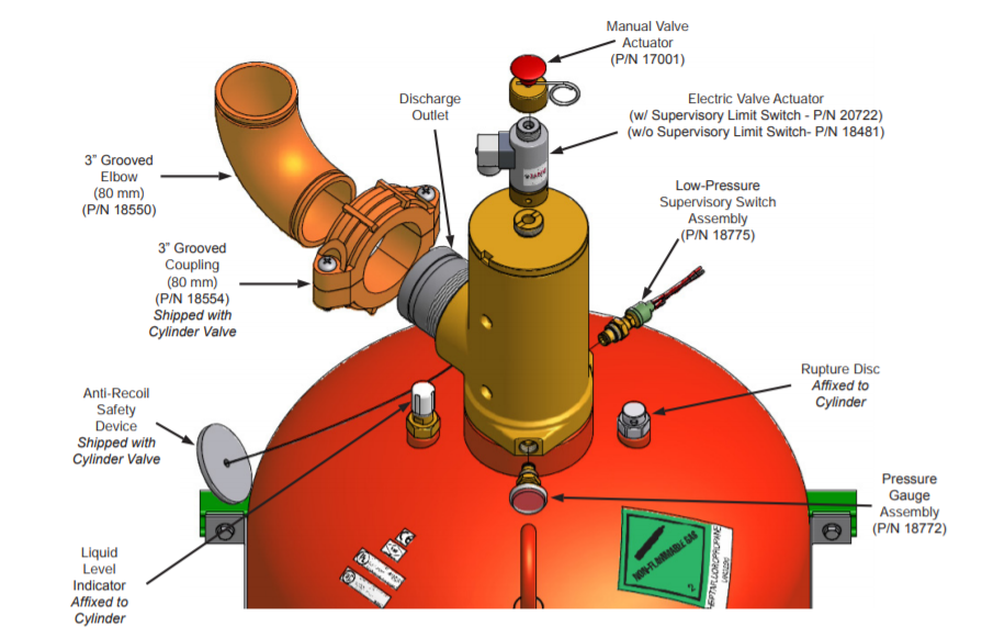
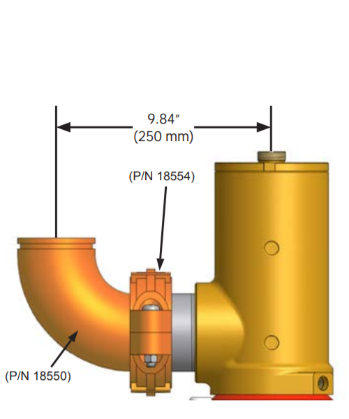
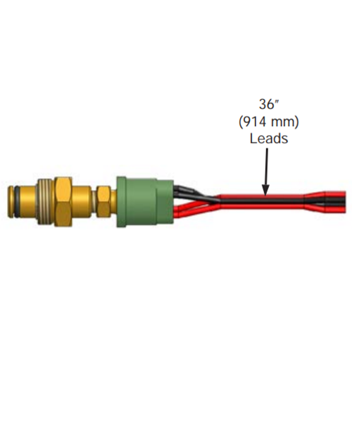
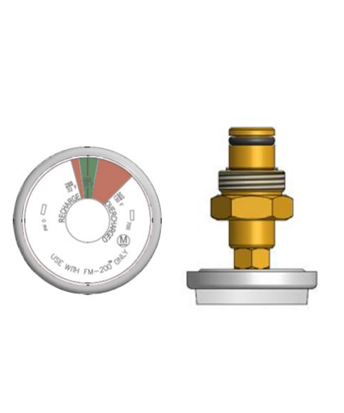
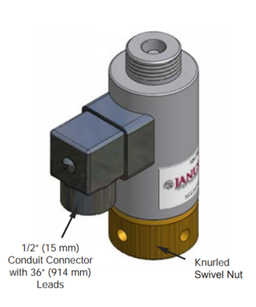
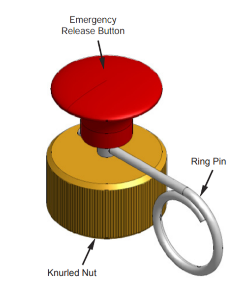
3. Trim Components

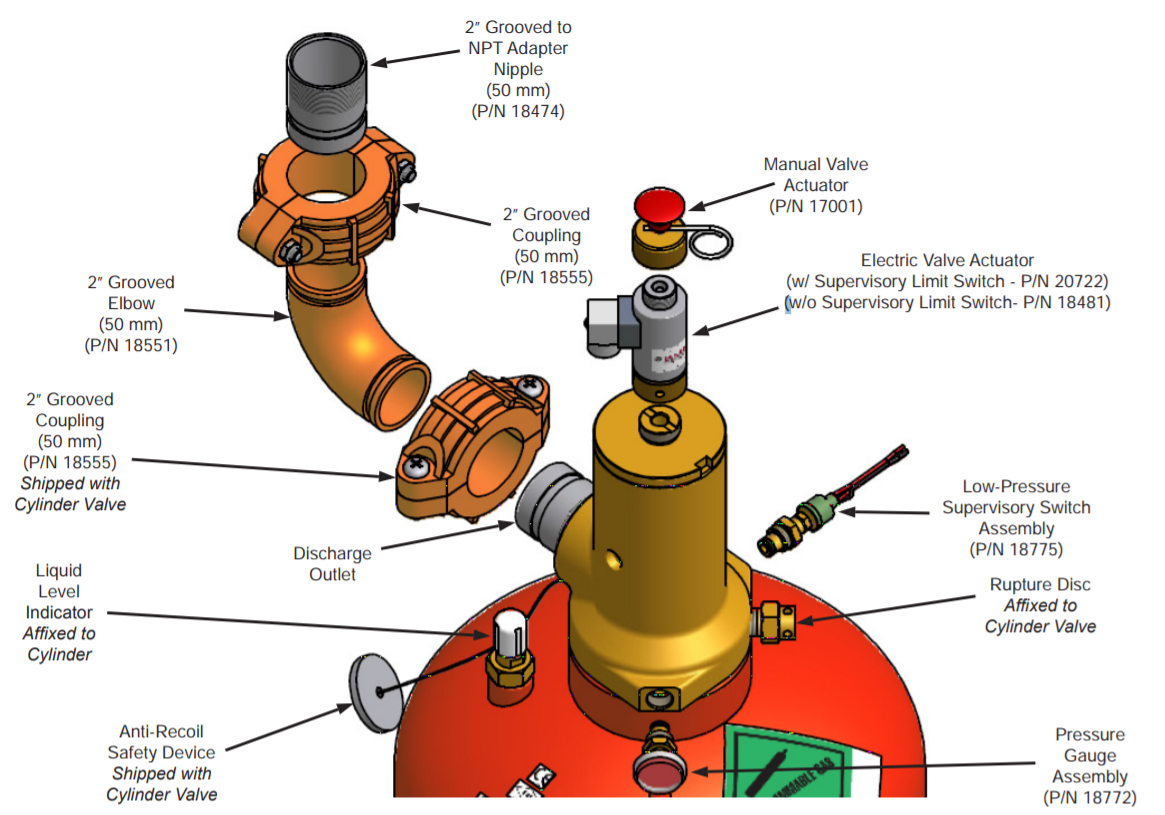
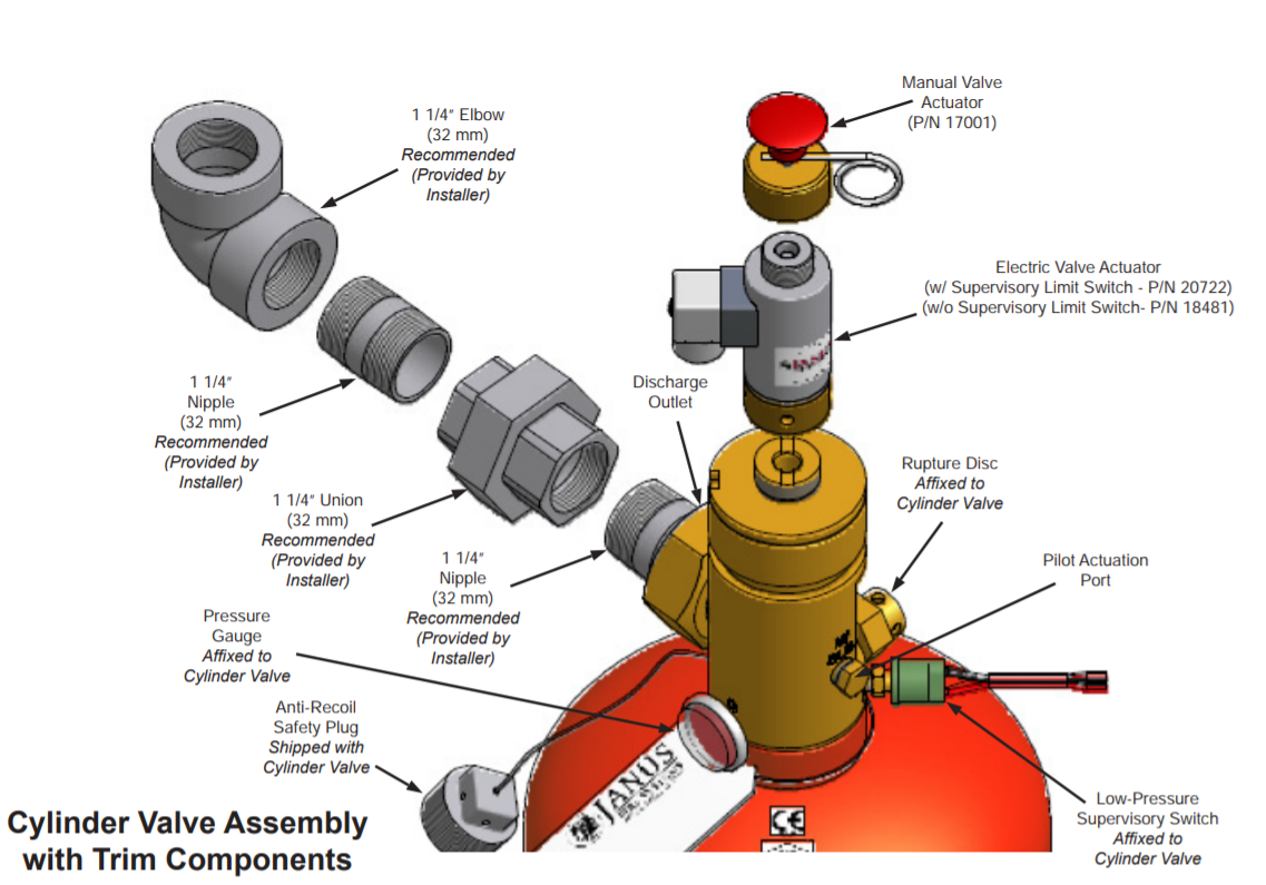
Trim components complete the installation of the FM-200® system and consist of connection fittings, pressure gauge, low-pressure supervisory switch, electric valve actuator, and manual valve actuator.

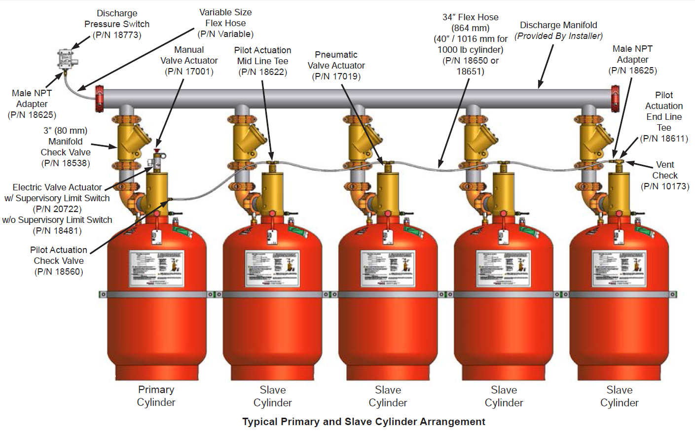
4. Slave Arrangement Components

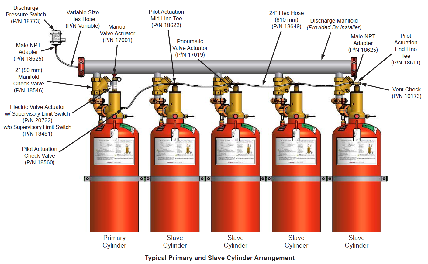
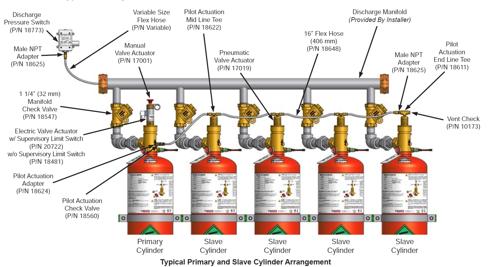
Slave arrangement components consist of the pneumatic valve actuator(s), actuation check valve, vent check, actuation hose, and fittings required for a multiple cylinder (slave) arrangement.

5. Supplemental Components

Supplemental components include the discharge pressure switch and manifold check valve. They supplement the core equipment or complete a specific multi-cylinder configuration.

6. Control Panel

This device monitors the condition of the electric actuator, detectors, warning devices, cylinder pressure, and any manual release and abort stations. All electric or electronic devices must connect to the control panel in order to function.

7. Early Warning Detection and Alarm Devices

Early warning detection devices coupled with manual release and abort stations maximize system efficiency while audible and visual alarm devices alert staff of alarm conditions.

FM-200® stored in steel cylinders fitted with forged brass, differential pressure-operated valves. Three valve sizes (Sv, Mv, and Lv Series)

Lv Series System
Mv Series System
Sv Series System

Lv SERIES

EQUIPMENT DESCRIPTION

The FM-200® agent is stored as a liquid in cylinder assemblies designed specifically for the application and charged to a fill density of between 35 lb/ft3
(561 kg/m3) and 70 lb/ft3 (1121 kg/m3 ). To ensure optimal performance, each cylinder is superpressurized with dry nitrogen to 360 psi (24.8 bar) at 70°F (21°C). An identification label is affixed to the cylinder body indicating the fill quantity of FM-200®, charging pressure, date of fill, and fill station. The Lv Series supports three cylinder capacities.

CYLINDER MOUNTING

Wall Mount Cylinder Bracket Assembly

Cylinder stability is ensured by the cylinder bracket assembly, consisting of one strap and rail with accompanying bolts, nuts, and washers. The rail is slotted for ease of mounting with fasteners provided by the installer.

Click to download Datasheet:

TRIM COMPONENTS

Trim components are required to operate the FM-200® cylinder(s).

SLAVE ARRANGEMENT COMPONENTS

Up to 16 cylinders (1 primary and 15 slave) may be installed in a single arrangement, with a maximum length of 100 ft (30.48 m) of pilot actuation hose or tubing extending from the primary cylinder in either direction. A typical arrangement is shown below.

Mv SERIES

EQUIPMENT DESCRIPTION

The FM-200® agent is stored as a liquid in cylinder assemblies designed specifically for the application and charged to a fill density of between 35 lb/ft3
(561 kg/m3 ) and 70 lb/ft3 (1121 kg/m3). To ensure optimal performance, each cylinder is superpressurized with dry nitrogen to 360 psi (24.8 bar) at 70°F (21°C). An identification label is affixed to the cylinder body indicating the fill quantity of FM-200®, charging pressure, date of fill, and fill station. The Mv Series supports two cylinder capacities.

CYLINDER MOUNTING

Wall Mount Cylinder Bracket Assembly (P/N 18535)

Cylinder stability is ensured by the cylinder bracket assembly, consisting of one strap and rail with accompanying bolts, nuts, and washers. The rail is slotted for ease of mounting with fasteners provided by the installer

Click to download Datasheet:

TRIM COMPONENTS

Trim components are required to operate the FM-200® cylinder(s).

SLAVE ARRANGEMENT COMPONENTS

Up to 16 cylinders (1 primary and 15 slave) may be installed in a single arrangement, with a maximum length of 100 ft (30.48 m) of pilot actuation hose or tubing extending from the primary cylinder in either direction. A typical arrangement is shown below.

Sv SERIES

EQUIPMENT DESCRIPTION

The FM-200® agent is stored as a liquid in cylinder assemblies designed specifically for the application and charged to a fill density of between 35 lb/ft3
(561 kg/m3 ) and 70 lb/ft3 (1121 kg/m3). To ensure optimal performance, each cylinder is superpressurized with dry nitrogen to 360 psi (24.8 bar) at 70°F (21°C). An identification label is affixed to the cylinder body indicating the fill quantity of FM-200®, charging pressure, date of fill, and fill station. The Mv Series supports two cylinder capacities.

CYLINDER MOUNTING

Wall Mount Cylinder Bracket Assembly (P/N 18595)

Cylinder stability is ensured by the cylinder bracket assembly, consisting of one strap and rail with accompanying bolts, nuts, and washers. The rail is slotted for ease of mounting with fasteners provided by the installer

Click to download Datasheet:

TRIM COMPONENTS

Trim components are required to operate the FM-200® cylinder(s).

SLAVE ARRANGEMENT COMPONENTS

Up to 16 cylinders (1 primary and 15 slave) may be installed in a single arrangement, with a maximum length of 100 ft (30.48 m) of pilot actuation hose or tubing extending from the primary cylinder in either direction. A typical arrangement is shown below.

TYPICAL AREAS OF FIRE PROTECTION

  • Telecommunication facilities
  • Computer rooms
  • Control rooms
  • Museums
  • Historical archive storage
  • Art galleries
  • Pharmaceutical and medical facilities
  • Record storage facilities
  • Offshore Platforms
  • Engine/Generator Rooms on Marine Vessels
  • Bridges of Ships

Protecting People, Assets, and the Environment.

Engineered Fire Protection Systems and Solutions Janus Fire Systems is a full service fire protection company committed to providing:

Quality products

Personalized Customer Care

Unsurpassable Innovation

Customer Training & Education

On-time shipping